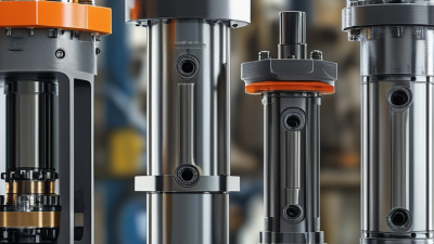
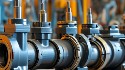
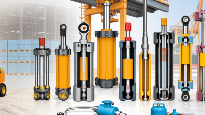
Choosing the right Hydraulic Cylinders begins with the work the machine must perform, not the catalog photograph. A cylinder lifting a loaded platform faces different demands from one steering a mobile machine or clamping a fixture. Record the required force, stroke, operating pressure, speed, duty cycle, and mounting arrangement. Then check the available space: a few millimeters around a clevis or rod end can decide whether the design fits.
Hydraulic systems engineer Dr. Peter Nachtwey is known for his practical work in motion control. A useful selection principle, consistent with that engineering approach, is: “Match the cylinder to the load, motion, and operating conditions—not just the bore size.” Treat that as a design reminder, not a substitute for verified specifications. Bore and rod diameter affect force and stability; stroke and mounting geometry shape alignment and side loading. Seal materials also matter when temperature, fluid type, or contamination may vary.
Small details count. A rod exposed to dust, a cylinder mounted at an angle, or repeated end-of-stroke impacts can shorten service life. It is easy to focus on peak force and overlook these everyday conditions. That is a common mistake. Confirm the load path, pressure limits, connection sizes, and maintenance access with the equipment manufacturer or a qualified hydraulic specialist. Ask for documented ratings, dimensional drawings, and application guidance before ordering. A careful choice may take longer, but it can prevent a costly mismatch once the machine is already assembled.
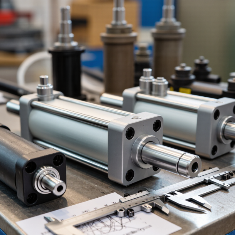
How to Choose the Right Hydraulic Cylinder?
Start with the real load, not just the machine’s rated capacity. A cylinder’s theoretical push force equals pressure multiplied by piston area; usable force is lower because of friction and pressure losses. Check both extension and retraction forces, since the rod reduces the effective area on the retract stroke. Then define the motion: required stroke, travel speed, cycle frequency, and whether the load moves smoothly or hits hard stops. A slow lift and a fast, shock-loaded clamp need different designs.
Operating conditions matter just as much. Record working pressure, fluid temperature, duty cycle, available space, mounting points, and exposure to dust or moisture. Fluid cleanliness also affects reliability. ISO 4406:2021 uses particle-count codes; for example, 18/16/13 corresponds to defined particle concentration ranges at 4, 6, and 14 micrometers. Treat that as a measurement reference, not a universal cleanliness target: the appropriate level depends on the components and system requirements. A calculation can look tidy and still miss impact loads or side-loading.
Tips: Measure the load at the cylinder, not at the machine’s motor. Note peak pressure and temperature during a full work cycle. If the cylinder rod may bend under compression, check buckling with the actual mounting arrangement. It’s easy to overlook.

Choosing a hydraulic cylinder starts with its motion and load, not just its bore size. A single-acting cylinder uses pressure in one direction and relies on gravity or a spring for return. A double-acting model controls motion both ways, which suits equipment that must retract under load. For frequent cycles, compare duty, stroke, and available space before choosing a compact or heavier-duty construction. Small details matter.
Next, match the mounting style to how the cylinder moves. Clevis and trunnion mounts allow pivoting, making them useful when the load follows an arc. Flange or foot mounts hold the cylinder more rigidly, but poor alignment can create side loads and wear seals. Check the geometry. The rod should travel along the load’s line of force, with pins and brackets sized for the expected forces.
Measure the closed and extended lengths, pin-center locations, and clearance around hoses before ordering. A tape measure and a simple layout drawing can catch clashes with frames or guards. Still, a sketch can miss flex under real load; verify alignment on the machine where possible. If the application has shock loads or long unsupported strokes, have the mounting and rod stability reviewed by a qualified hydraulic professional.
Bore size starts with the force required at the working pressure. Use F = P × A, then allow for friction and pressure losses; a bore that works on paper may still stall under load. For a 20 kN push at 16 MPa, the ideal bore is about 40 mm, before allowances. ISO 6020-1:2007 defines a 16 MPa nominal-pressure cylinder series. That is a design reference, not proof that every installation can safely run at that pressure. Check the cylinder rating and the whole circuit.
Rod diameter needs a separate check. During extension, the rod sees compression, so a long stroke can buckle even when the bore delivers enough force. Compare the extended length, mounting style, load direction, and operating pressure against a recognized buckling calculation. A side load from a misaligned clevis can also wear seals and score the rod. Check both. A larger rod can improve stability, but it reduces retract-side piston area and may slow retraction.
Set stroke length from the machine’s measured travel, not a drawing alone. Include stop positions, linkage movement, and any required cushioning distance. Leave room for installation and end fittings. This is an easy detail to miss. Recheck the retract force using the annular area: piston area minus rod area. If the load changes direction or speed, verify both strokes under those conditions; the first sizing pass is rarely the whole answer.
How to Choose the Right Hydraulic Cylinder?
Match the cylinder’s pressure rating to normal operating pressure and measured pressure spikes, not just the pump’s nameplate figure. Repeated overloads can damage the barrel, rod, or seals. Check the duty cycle, too: a cylinder moving heavy loads all day faces different demands from one used occasionally. Field measurements are often messier than the design brief.
Environment changes material and seal choices. Carbon steel suits many indoor applications, while corrosion-resistant finishes or stainless steel may be better around moisture and washdown. Nitrile seals work with many mineral oils; higher temperatures or aggressive fluids may call for another elastomer, confirmed against the fluid supplier’s compatibility data. ISO 4406:2021 classifies hydraulic-fluid contamination; code 18/16/13 corresponds to roughly 1,300–2,500 particles of 4 μm or larger per millilitre. This is a cleanliness classification, not a universal target. Follow the system maker’s specification.
Tips: Record peak pressure, fluid temperature, and exposure conditions. Inspect rod seals for dust, scoring, or leakage after installation. Small details matter. Measure, then verify.
Typical operating temperature ranges for common hydraulic seal materials
Temperature ranges are typical guidance and vary by compound, fluid, pressure, and duty cycle. Choose a cylinder pressure rating that meets or exceeds the system’s maximum pressure, and confirm seal and cylinder materials are compatible with the fluid and operating environment.
Choosing a hydraulic cylinder starts with matching its bore, stroke, mounting style, and pressure rating to the machine. Measure the available space between pin centers, then check the load and operating speed under real working conditions. A cylinder that fits on paper may bind when the frame flexes. That detail is easy to miss. Match the rod end and port type to existing connections, and confirm the fluid and seal materials suit the operating temperature.
Maintenance access matters, too. Can a technician inspect the rod for scratches, wipe away grit, and reach fittings without removing nearby guards? Record leakage, noise, and cycle time; small changes can reveal wear before a failure stops production. The U.S. Bureau of Labor Statistics reported 2.6 million nonfatal workplace injury and illness cases in private industry in 2023. That figure is not specific to hydraulic equipment, but it reinforces the value of practical safeguards and routine checks.
For safety, select a cylinder rated above the system’s maximum working pressure, including expected pressure spikes. Use load-holding devices where a suspended load could drop, and never rely on trapped fluid alone. ISO 4413:2010 sets safety requirements for hydraulic fluid power systems, including pressure protection and safe maintenance practices. Verify the machine’s relief-valve setting, hose rating, and guarding against the cylinder specification. I would recheck the load assumptions after any machine change; that step is sometimes skipped.