Blog

How to Manufacture Hydraulic Cylinders in 2026?

Manufacturing Hydraulic Cylinders in 2026 requires more than cutting steel and installing seals. It demands controlled design, traceable materials, accurate machining, and verified performance under pressure. Grand View Research estimated the global hydraulic cylinder market at approximately USD 14.8 billion in 2023, with continued growth expected through 2030. MarketsandMarkets also identifies construction, agriculture, mining, and material handling as major demand sectors. The figures are not perfectly aligned. Definitions and regional coverage differ between reports. Still, the direction is clear: buyers increasingly expect stronger, smarter, and more efficient cylinders.

A reliable production line begins with application data. Bore diameter, stroke length, working pressure, side loads, temperature, and duty cycle must be confirmed before fabrication. Engineers typically select seamless or honed tubes, induction-hardened rods, precision-fitted pistons, and seals matched to the fluid and temperature range. Small errors matter. A rough rod surface can damage a seal, while poor weld penetration may create leakage or structural weakness. ISO 9001 quality systems, ISO 6020/2 or ISO 6022 dimensional practices, and documented pressure testing support consistent results. In practice, however, standards alone cannot replace skilled inspection. Each cylinder should receive material verification, dimensional checks, cleanliness control, and a recorded hydrostatic test. This guide examines the complete manufacturing route, from engineering and sourcing to machining, assembly, testing, and maintenance. Some assumptions may need revision. Real operating conditions often expose weaknesses that drawings never show.

How to Manufacture Hydraulic Cylinders in 2026?

Hydraulic Cylinder Types, Components, and Design Requirements

How to Manufacture Hydraulic Cylinders in 2026?

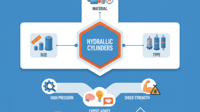
Hydraulic-cylinder manufacturing begins with the working conditions, not the drawing. Single-acting cylinders handle force in one direction. Double-acting cylinders control extension and retraction. Telescopic cylinders provide long strokes in limited spaces. Tie-rod designs support easier maintenance. Welded cylinders suit high loads and compact machinery. Grand View Research estimated the global hydraulic-cylinder market at about USD 14 billion in 2023. Its report projects steady growth through 2030. Other studies forecast different values. That difference deserves caution.

A reliable cylinder needs a honed barrel, piston, rod, seals, gland, ports, and mounting points. Each component affects leakage, friction, and service life. Rod diameter must resist bending and buckling during peak loads. Seal selection depends on pressure, temperature, speed, and fluid compatibility. ISO 6020/2 and ISO 6022 define important mounting and dimensional requirements. ISO 3320 also supports consistent cylinder interfaces. These standards reduce redesign work, but they cannot replace field experience.

Manufacturing quality depends on controlled boring, honing, welding, heat treatment, and surface finishing. Rod surfaces require precise roughness, because excessive texture damages seals. Each assembled cylinder should undergo pressure, leakage, stroke, and functional testing under ISO 10100 practices. MarketsandMarkets reported continued demand from construction, agriculture, and material-handling equipment in its 2024 hydraulic equipment study. Yet real applications remain unpredictable. Dust, side loading, poor alignment, and contaminated oil can defeat an excellent design. Engineers should leave room for inspection, repair, and uncomfortable lessons from failed prototypes.
Material Selection and Preparation for Hydraulic Cylinder Manufacturing

How to Manufacture Hydraulic Cylinders in 2026?

Material selection determines whether a hydraulic cylinder survives pressure, vibration, and repeated loading. The barrel usually requires honed carbon steel or alloy steel with consistent wall thickness. Rods need high tensile strength, surface hardness, and controlled straightness. Stainless steel can help in corrosive environments, but it may increase cost and machining difficulty.

Do not trust appearance alone. Verify mill certificates, chemical composition, yield strength, and heat-treatment records before cutting stock. Inspect each tube for pits, laminations, and internal scale. Clean the material carefully, then leave enough machining allowance for boring and honing. Rod blanks should be stress-relieved when necessary. Otherwise, distortion may appear after turning. A common mistake is choosing a stronger alloy without checking weldability or seal compatibility.

Tips: Keep material batches traceable. Measure hardness at several points, not just one. Protect prepared rods from dust and moisture. Use calibrated gauges. Small errors matter. Experienced teams also test sample parts before full production, especially when changing suppliers or heat treatments. This step may feel slow, but it can reveal hidden cracking, unstable dimensions, or poor surface finish. Material planning is never perfect; actual workshop feedback should revise future specifications.

Material Selection for Hydraulic Cylinder Manufacturing in 2026

Typical engineering values show why medium-carbon and alloy steels are widely selected for hydraulic cylinder barrels, rods, and mounting components. Alloy steel such as AISI 4140 provides higher yield strength after heat treatment, while AISI 1020 and AISI 1045 offer easier machining and lower material cost. Stainless steel is selected where corrosion resistance is more important than maximum strength. Values are representative typical ranges and should be verified against the applicable material standard and supplier certificate before production.

Machining and Fabricating the Cylinder Components

Hydraulic cylinder manufacturing starts with disciplined machining of each component. The barrel is usually cut from honed steel tubing or machined from solid stock. Its bore must remain straight, smooth, and consistent across the full length. Even a small internal mark can damage a seal during service. I have found that careful setup matters more than aggressive cutting speed. Boring tools need sharp edges, stable clamping, and measured tool compensation. Check the bore with calibrated gauges, not visual judgment alone. That mistake is common.

The piston rod requires accurate turning, thread cutting, and surface finishing. Its polished section should resist wear without becoming excessively rough. Grinding can improve the finish, but overheating may weaken the surface. The piston, gland, head, and end cap also need controlled fits and clean sealing grooves. During fabrication, weld preparation affects alignment and strength. Remove scale, control heat input, and inspect every joint for distortion. Welding first and correcting alignment later is risky. Sometimes, production pressure encourages shortcuts. Those shortcuts should be recorded and reviewed, because a cylinder may pass a quick inspection yet fail under repeated loads. Final assembly demands lint-free cleaning, correct seal orientation, and gradual pressure testing. Measure leakage, rod movement, and pressure stability under realistic conditions. Mistakes are useful only when they become process improvements.

How to Manufacture Hydraulic Cylinders in 2026? – Machining and Fabricating the Cylinder Components
Manufacturing Stage Cylinder Component Typical Material Main Machining or Fabrication Operation Typical Engineering Data Quality-Control Check
1. Material Preparation Tube, rod, piston and end-cap blanks Seamless or welded steel tube; medium-carbon or alloy steel bar Cutting with a band saw, circular saw or automated cold saw; batch identification and end squaring Cut-length tolerance: typically ±0.5 to ±1.0 mm, depending on component size Material certificate review, grade verification, visual inspection and dimensional measurement
2. Cylinder Tube Preparation Pressure tube Cold-drawn honed tube or precision steel tube Facing, chamfering, external turning, internal boring and preparation for honing Common internal diameter range: approximately 25–500 mm; tube wall thickness often 3–40 mm Internal diameter, wall thickness, straightness, roundness and surface defects
3. Internal Honing Tube bore Hardened or honed steel tube Precision honing with progressively finer abrasive stones to create a controlled cross-hatch pattern Typical bore surface roughness: Ra 0.2–0.8 µm; common bore tolerance: approximately ISO H8–H9 Bore gauge measurement, roughness measurement, roundness check and visual inspection of the cross-hatch
4. Rod Turning Piston rod Medium-carbon or alloy steel, usually selected for strength and fatigue resistance CNC turning, center drilling, shoulder machining, thread cutting and end-feature machining Common rod diameter range: approximately 12–300 mm; diameter tolerance often within 0.02–0.10 mm Diameter, concentricity, thread dimensions, shoulder geometry and straightness
5. Rod Surface Treatment Exposed piston rod surface Steel rod with hard-chrome, electroless-nickel or other specified corrosion-resistant coating Grinding and polishing before coating; controlled plating or coating; post-treatment polishing when required Typical hard-chrome thickness: approximately 20–50 µm; finished roughness commonly Ra 0.1–0.3 µm Coating thickness, adhesion, surface roughness, diameter, pits, cracks and corrosion resistance
6. Piston Manufacturing Piston Steel, ductile iron or aluminum alloy, selected according to pressure and mass requirements CNC turning, groove machining, drilling, keyway or anti-rotation-feature machining Piston-to-bore running clearance is commonly designed in the hundredths-of-a-millimeter range Outside diameter, groove width and depth, concentricity, weight and compatibility with piston seals
7. Piston-Rod Connection Rod-to-piston joint Compatible steel grades with controlled thread or fitted-joint design Threading, shoulder fitting, welding or mechanical locking, depending on cylinder architecture Thread dimensions and tightening torque must be defined by the design drawing and load calculation Thread gauge inspection, runout measurement, joint torque verification and non-destructive testing where specified
8. Gland and Guide Fabrication Rod gland, guide bushing and seal carrier Steel, bronze, sintered metal or engineered polymer, depending on load and lubrication conditions CNC turning, boring, seal-groove machining, retaining-ring grooves and lubrication-passage machining Guide clearance is application-specific and is normally controlled at a few hundredths of a millimeter Seal-groove profile, guide-bushing fit, bore size, concentricity and burr removal
9. End-Cap Fabrication Front and rear end caps Carbon steel, alloy steel or ductile iron CNC milling and turning, port drilling, threaded-hole machining, mounting-feature fabrication and sealing-surface finishing Port type and size are selected according to flow rate, working pressure and connection standard Mounting dimensions, port geometry, thread inspection, sealing-face flatness and pressure-boundary integrity
10. Welding and Assembly Preparation Welded tube, caps, brackets and mounting attachments Weld-compatible carbon or low-alloy steel Fixture alignment, robotic or manual welding, controlled heat input, stress relief when required, cleaning and deburring Weld procedure qualification, preheat and interpass temperatures are determined by material grade and wall thickness Weld visual inspection, dimensional alignment, dye penetrant or magnetic-particle testing where required
11. Sealing-System Installation Piston seal, rod seal, wiper, wear ring and static seals Polyurethane, nitrile rubber, fluorocarbon rubber, PTFE or other application-approved materials Cleaning, controlled lubrication, seal installation with non-damaging tools and orientation verification Seal material is selected according to pressure, temperature, fluid compatibility and sliding speed Seal size, orientation, groove cleanliness, extrusion gaps and damage inspection
12. Final Cylinder Assembly Complete hydraulic cylinder Machined and treated components assembled with compatible hydraulic seals Insertion of piston and rod assembly, gland installation, cap fastening, port protection and final torque control Assembly cleanliness target is defined by the hydraulic system cleanliness requirement, commonly using an ISO 4406 code Stroke length, retracted and extended dimensions, mounting alignment, torque records and freedom of movement
13. Pressure Testing Pressure boundary and seals Fully assembled cylinder filled with the specified test fluid Air bleeding followed by hydraulic proof, leakage and functional testing on a calibrated test bench Proof-test pressure is commonly set above rated working pressure according to the applicable design specification External leakage, pressure drop, drift, abnormal noise, full-stroke operation and permanent deformation
14. Surface Protection External tube, caps and mounting components Prepared carbon or alloy steel Degreasing, abrasive preparation, phosphate treatment, powder coating, liquid painting or corrosion-protection treatment Coating thickness is specified by the service environment and coating system; exposed rod surfaces require separate protection Coating thickness, adhesion, coverage, color uniformity, corrosion protection and masked-surface condition
15. Final Inspection and Traceability Finished hydraulic cylinder Completed product with documented material and process history Dimensional inspection, marking, protective packaging and production-record completion Inspection records typically include serial traceability, critical dimensions, test pressure and test results Final drawing compliance, identification marking, cleanliness, documentation completeness and packaging integrity
Typical values are engineering reference ranges only. Final dimensions, materials, tolerances, test pressures and surface treatments must be established from the cylinder design, operating conditions, applicable standards and customer specifications.

Assembly, Sealing, and Surface Treatment Procedures

Hydraulic cylinder manufacturing in 2026 depends on disciplined assembly, reliable sealing, and controlled surface treatment. Each machined tube is cleaned before assembly, removing chips, abrasive dust, and microscopic oil sludge. Technicians check bore size, rod straightness, and gland alignment with calibrated instruments. Small errors matter.

During assembly, seals are installed with clean tools and approved lubricants. Cutting a seal during installation can create a leak that appears only under pressure. Backup rings, wipers, and guide rings must face the correct direction. The piston nut receives a controlled tightening torque, then its position is recorded for traceability. Assemblers should never force parts into place. That usually hides a deeper alignment problem.

Surface treatment protects the rod from corrosion, wear, and repeated contact with the wiper. Depending on operating conditions, the rod may receive hardened plating, engineered coatings, or another qualified treatment. The finished surface must be smooth, uniform, and free from pits or peeling. Operators inspect coating thickness at several points, not only near the rod end. After assembly, the cylinder undergoes low-pressure movement checks and a documented pressure test. Clean oil is essential during testing.

One practical lesson remains: rushing the final inspection can erase the value of careful machining. Some workshops still treat cleaning as routine, but contamination remains one of the most common causes of early seal failure.

Pressure Testing, Quality Inspection, and Final Packaging

How to Manufacture Hydraulic Cylinders in 2026?

Pressure testing begins after assembly, cleaning, and air removal. Technicians fill each cylinder with filtered hydraulic fluid. Trapped air can create unstable readings and hide leakage. The cylinder then faces the approved test pressure for a controlled period. Gauges record pressure loss, rod movement, and visible seepage around seals. Test data is linked to the cylinder’s production number. This creates a traceable record for later service checks.

Quality inspection continues beyond the test bench. Inspectors measure bore diameter, rod straightness, surface finish, and mounting dimensions. They examine welds for cracks, pinholes, and uneven penetration. Seal grooves receive special attention because small burrs can damage new seals. Digital tools improve consistency, but trained judgment remains necessary. No inspection system is flawless. A faint scratch may escape notice under poor lighting.

Final packaging protects the cylinder from moisture, impact, and contamination. Workers cap hydraulic ports, apply corrosion protection, and secure the rod against movement. Thick wrapping shields painted surfaces during transport. A label records the model, test status, handling direction, and inspection date. Packaging teams should check every crate before release. We still review damaged cartons, because they reveal weak points in handling. Better protection often begins with one overlooked mark.