Blog

How to Choose the Right BESS Connector?

Choosing the right Bess Connector is a practical design decision, not a cosmetic one. It affects how battery modules, power conversion equipment, and service teams connect in real operating conditions. A connector that fits on a drawing may still be difficult to install beside a crowded rack or inspect after months of use. Small details matter.

Start with the system’s specified voltage, continuous and peak current, cable size, and expected operating temperature. These values should come from the equipment design and manufacturer documentation, not guesswork. Check the connector’s contact resistance, locking method, polarity protection, and rated mating cycles. Then consider the installation environment: dust, moisture, vibration, and limited access can change what works well. For outdoor or demanding sites, confirm the enclosure protection and temperature limits for the exact connector assembly.

Compatibility deserves careful attention. Similar-looking parts may use different contact geometries or cable terminations. A mismatch can create installation problems and unreliable connections. Verify the connector model, conductor range, and crimping or assembly method with the supplier’s technical data. Ask how the connection will be inspected, disconnected, and replaced during maintenance. It is easy to focus on current ratings and overlook service access.

There is no single best choice for every BESS. Compare documented specifications against the actual duty cycle, site conditions, and maintenance plan. If the design leaves uncertainty, pause and confirm it with a qualified electrical engineer or the equipment manufacturer. A little extra checking now can prevent a poor fit later.
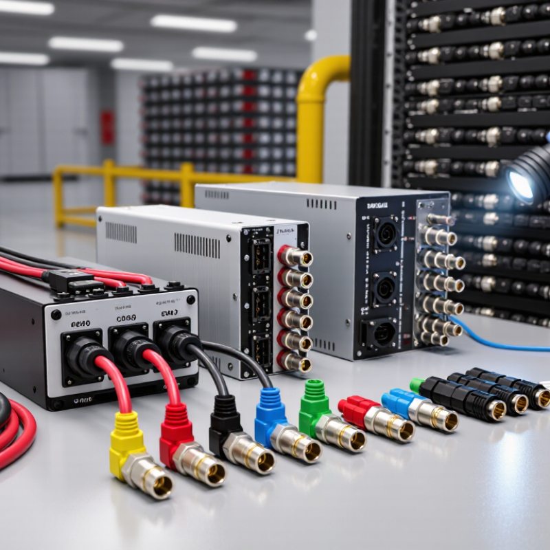
How to Choose the Right BESS Connector?

Understand the Connector’s Role in a BESS

A BEss Connector is more than a link between two cables. It creates a controlled electrical path between battery modules, racks, and, depending on the system design, power conversion equipment. That path must carry the specified current while limiting resistance, heat, and the risk of accidental contact. Small interface, large responsibility.

During operation, even a slight increase in contact resistance can create localized heating. A technician may notice a warm connector before any alarm appears, but temperature checks alone cannot confirm the cause. Correct assembly, compatible cable sizes, secure locking, and clean contact surfaces all matter. The connector also needs to withstand the installation environment, including vibration, dust, and moisture where applicable.

Its role continues during inspection and service. Clear polarity marking helps prevent connection errors, while a dependable locking feature can reduce the chance of a plug loosening under vibration. These details sound obvious; in the field, they are easy to overlook. Connector selection should match the system’s electrical ratings, cable arrangement, enclosure, and service plan. No single connector is right for every BESS configuration. A datasheet is useful, but it cannot replace checking the actual installation conditions.

Identify System Requirements and Operating Conditions

Before selecting a BESS connector, map the electrical demands at the point where it will operate. Record the system’s maximum DC voltage, continuous current, and expected peak current. Check the battery’s fault-current data and the protection devices used with the connection. A connector’s current rating can change with cable size, ambient temperature, and installation method. Small details matter. A cable routed through a warm, crowded enclosure may need more careful derating than one in open air.

Then assess the physical environment and service routine. Note likely exposure to dust, condensation, vibration, and repeated temperature changes. Check the connector’s specified temperature range, ingress protection, locking method, and mating compatibility; similar-looking parts are not automatically interchangeable. Confirm conductor size, contact material, and termination method against the equipment documentation. A neat spreadsheet can still miss a tight bend radius or limited hand clearance. Measure the actual space, and consider whether technicians can inspect and disconnect the assembly safely. If operating conditions are uncertain, document the assumptions and ask the system designer or connector supplier to verify them before installation. That is not enough by itself. Recheck ratings after any change to the cable route or enclosure.

Compare Connector Types, Materials, and Interfaces

BESS connector selection starts with the interface. Bolted busbar connections suit fixed assemblies, while plug-in connectors can simplify module replacement. Stud terminals are common where cables need a secure mechanical attachment. Match the connector to the equipment’s specified voltage, continuous current, cable size, and available space. Fit matters. A connector that looks correct may still have the wrong contact geometry or polarity. Check the datasheet and confirm compatibility with the actual mating part.

Material choices affect performance over time. Copper offers good conductivity; plating, such as tin, can help limit surface oxidation in suitable environments. For aluminum cables, use terminals explicitly rated for aluminum and follow the specified installation method. Mixed metals can create corrosion concerns if the interface is poorly designed. Look for temperature ratings, ingress protection, touch protection, and approved crimping or torque requirements. Small mismatch, real heat. I would also verify that the rating applies to the complete connection, not just one component.

Tips: Compare connector drawings, not just product names. Check cable entry direction, locking features, and service clearance. Confirm that mating parts share the same interface standard. Recheck torque with the specified tool; guessing is not a reliable shortcut. A connector may pass an initial fit check yet loosen under vibration, so installation quality deserves a second look.

Check Electrical Ratings, Safety, and Environmental Protection

How to Choose the Right BESS Connector?

A BESS connector must match the system’s electrical demands, not just fit the cable. Check its rated DC voltage and continuous current against the battery and inverter specifications. Account for short-duration current peaks and temperature derating; a rating measured in cool laboratory conditions may not suit a hot enclosure. Confirm the connector’s short-circuit capability and compatible cable size, too. Small details matter. A loose or poorly crimped contact can create resistance, heat, and gradual damage. Follow the connector maker’s installation instructions, and use the specified crimping tool.

Tips: Compare ratings at the expected operating temperature. Verify polarity, keying, and locking features before energizing the circuit. Inspect contact surfaces for contamination, then check that the connection is fully seated. It is easy to rush this step.

Safety and environmental protection need equal attention. Look for touch-safe designs and clear provisions for preventing accidental disconnection under load. Check the ingress-protection rating against the actual location: dust, water spray, and condensation pose different risks, and an IP rating does not automatically mean immersion is safe. Consider corrosion near coastal sites, UV exposure outdoors, and vibration in mobile or industrial installations. Not every site is clean. Review the datasheet alongside the enclosure design and maintenance plan; real conditions can be messier than the specification sheet suggests.

How to Choose the Right BESS Connector? - Check Electrical Ratings, Safety, and Environmental Protection

Selection Factor What to Check Selection Rule Useful Evidence
Rated voltage The connector’s rated DC voltage and the battery system’s maximum operating voltage, including the highest permitted state of charge and charging conditions. Choose a connector whose DC rating is suitable for the system’s maximum voltage. Do not rely on an AC voltage rating as proof of an adequate DC rating. Manufacturer datasheet showing the DC voltage rating and applicable operating conditions.
Continuous and peak current Maximum continuous current, expected charge and discharge current, short-duration peaks, ambient temperature, conductor size, and installation conditions. The allowable current must cover the application after any applicable temperature, cable-size, or installation derating. Check both continuous and time-limited ratings. Current-rating curves or derating tables, plus the specified wire or busbar range.
DC switching capability Whether connection or disconnection under load is permitted at the system’s DC voltage and current. Treat the connector as non-load-break unless the manufacturer explicitly rates it for the required DC switching duty. Isolate the circuit before mating or unmating when required. Explicit load-break or switching rating, operating instructions, and any required interlock or isolation procedure.
Temperature and heating Specified ambient and conductor temperature limits, contact temperature rise, and the effects of enclosure temperature and nearby heat sources. Use the connector within its documented temperature limits and current derating conditions. Do not assume a rating measured under one test setup applies to every installation. Datasheet temperature range, derating information, and installation or thermal-test conditions.
Contact resistance and connection quality Contact resistance, termination method, conductor preparation, specified crimp tooling, and the effect of loose or improperly assembled connections. Follow the specified assembly process and use compatible conductors and tooling. Poor terminations can increase resistance and cause overheating. Assembly instructions, approved conductor range, tool requirements, and contact-resistance data where provided.
Touch protection and polarity Protection against access to live parts, connector keying, polarity identification, and the risk of accidental mating with an incompatible circuit. Select a design suitable for the installation’s access conditions, with clear polarity identification and mechanical keying where needed. Verify that mating parts are electrically and mechanically compatible. Product drawings, touch-protection details, keying information, and installation instructions.
Ingress protection Exposure to dust, water jets, rain, condensation, or temporary immersion, including whether the connector is mated or capped during exposure. Choose an IP rating appropriate to the actual environment and installation state. Under IEC 60529, IP6X indicates dust-tight protection; IPX7 relates to temporary immersion under specified test conditions and does not by itself establish suitability for continuous immersion. IP test rating and the test configuration, including whether the rating applies when mated, unmated, or fitted with a protective cap.
Corrosion and chemical exposure Humidity, salt exposure, cleaning agents, battery-room chemicals, and compatibility of contacts, plating, seals, and housing materials. Confirm material compatibility with the site environment; an ingress rating alone does not demonstrate resistance to corrosion or chemicals. Material specifications and test or compatibility information for the expected exposure.
Vibration and mechanical retention Vibration, cable movement, mating cycles, latch or locking features, and strain relief in the intended installation. Use a locking and strain-relief arrangement suited to the equipment layout and expected movement. Observe the specified mating-cycle limit and inspection schedule. Mechanical ratings, retention details, mating-cycle data, and mounting instructions.
Short-circuit protection coordination Available fault current, upstream fuse or circuit-breaker characteristics, and the connector assembly’s documented withstand capability. Coordinate the connector and conductors with the protective device. Do not assume the connector can interrupt or withstand a fault unless its documentation supports that duty. Fault-current and protective-device coordination information from the equipment design and connector documentation.
Standards and approvals Applicable connector standards, certification scope, system requirements, and local electrical codes. Confirm that the approval applies to the connector’s intended use, voltage, current, and installation conditions; verify requirements with the project’s authority having jurisdiction. Current certificates or declarations, standard references, and installation instructions.

Note: Connector ratings and test conditions vary by product. Use the project’s maximum operating values and the manufacturer’s documentation for final selection; this table is a screening guide, not a substitute for system design or code review.

Verify Compatibility, Installation, and Maintenance Needs

A BESS connector must match the electrical design, not just the cable end. Check the system voltage and continuous current rating, then allow for peak loads and the enclosure’s temperature range. Confirm conductor size, polarity, keying, and contact compatibility against the equipment documentation. A plug that fits can still create a poor electrical connection. That detail is easy to miss.

Installation needs matter just as much. Check whether the connector can be reached with the required crimping or tightening tools, and leave enough room for the cable’s bend radius. Follow the specified torque; overtightening can damage parts, while a loose joint may heat under load. Also verify the sealing method and ingress rating for the actual environment, especially where dust or moisture may collect. It is tempting to assume a higher rating solves every site problem. It does not.

Plan maintenance before choosing. Ask whether technicians can inspect the contact area without disturbing nearby cables, and whether replacement parts are readily identifiable. During scheduled inspections, look for discoloration, cracked housings, corrosion, damaged seals, and signs of looseness. Keep inspection intervals and isolation procedures aligned with the equipment instructions. A clean exterior proves little. Documenting the connector type and inspection findings helps prevent guesswork later, though records can be incomplete if no one owns the task.

How to Choose the Right BESS Connector

Verify compatibility, installation, and maintenance needs before selecting a connector.

Compatibility checks come first: confirm the connector’s voltage and current ratings, conductor range, and mating compatibility against the system design and manufacturer documentation. Also verify environmental suitability, installation requirements, and access for inspection. Scores show qualitative relative priorities on a 1–5 scale; they are guidance, not measured test results or universal ratings.

Article Source: