Blog

What Are the 2026 Top 3 Phase Brushless DC Motor Types?

Choosing a 3 Phase Brushless Dc Motor in 2026 requires more than comparing speed and price. Engineers now examine thermal paths, controller compatibility, acoustic noise, efficiency, and service life. A motor may look powerful on a specification sheet. Its real performance depends on the complete drive system.

R. Krishnan, a respected motor-drive researcher and author, describes the principle clearly: “A brushless DC motor is a permanent-magnet motor with electronic commutation.” This idea remains central, although modern products often blur the boundary between BLDC motors and permanent-magnet synchronous motors. The terminology is not always consistent. That can confuse buyers.

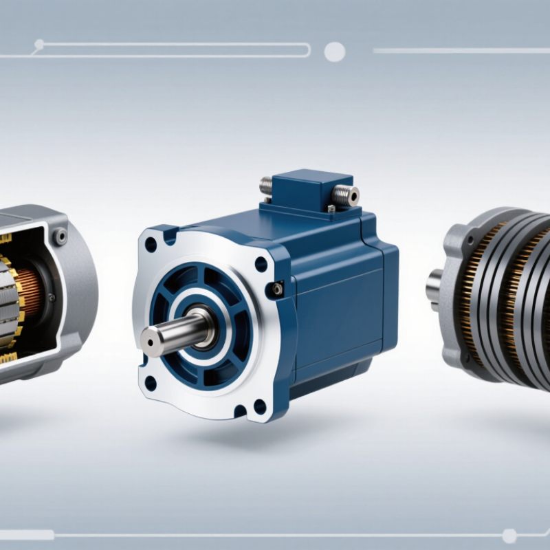
This guide examines three important 3 Phase Brushless Dc Motor types expected to remain influential in 2026: inner-rotor motors, outer-rotor motors, and axial-flux motors. Inner-rotor designs commonly support high speed and compact cooling arrangements. Outer-rotor versions can deliver strong torque in a short package, making them useful for fans, wheels, and robotic joints. Axial-flux designs offer a thin profile and promising torque density, but manufacturing complexity remains a serious limitation.

The best choice depends on the application.

A small robot may need rapid acceleration and precise position control. An electric fan may prioritize quiet operation and low cost. A traction system may demand continuous torque beside a reliable inverter. Laboratory ratings are useful, but they do not reproduce dust, vibration, heat, or imperfect installation. That gap deserves attention. This comparison therefore focuses on practical selection, not marketing claims, while recognizing that some 2026 technologies remain commercially immature.
What Are the 2026 Top 3 Phase Brushless DC Motor Types?

Three-Phase Brushless DC Motors: Definition and Operating Principles

Three-phase brushless DC motors use electronic commutation instead of mechanical brushes. Their stator contains three winding groups, spaced 120 electrical degrees apart. A permanent-magnet rotor follows the rotating magnetic field created by these windings. The controller switches current between phases according to rotor position. Hall sensors can provide that position. Sensorless systems estimate it from back electromotive force.

Three common types are sensored trapezoidal, sensorless trapezoidal, and sinusoidal three-phase motors. Sensored trapezoidal motors deliver strong starting torque and simple control. Sensorless versions reduce wiring, but low-speed starting can be less reliable. Sinusoidal motors produce smoother torque and quieter rotation, although their control software is more demanding. In practical testing, alignment errors, bearing friction, and heat can change results significantly. The specification sheet rarely tells the whole story.

The U.S. Department of Energy’s Motor Systems Market Assessment reports that motor-driven equipment consumes roughly half of global electricity. This makes efficiency more than a marketing detail. IEC 60034 test principles help engineers compare rated output, losses, temperature rise, and duty performance. A 2024 market analysis by Grand View Research also identified rising demand for brushless motors in vehicles, appliances, and industrial automation. However, market forecasts vary widely because analysts classify motors differently. That weakness deserves attention. A motor may be called “BLDC” in one report and “permanent-magnet synchronous” in another, despite similar construction. Engineers should verify back-EMF shape, commutation method, sensor arrangement, and operating duty before selecting a type.

How Electronic Commutation Controls Three-Phase BLDC Motors

What Are the 2026 Top 3 Phase Brushless DC Motor Types?

Electronic commutation replaces mechanical brushes with semiconductor switches and precise rotor-position feedback. In a three-phase BLDC motor, the inverter energizes selected windings in a timed sequence. This creates a rotating magnetic field and steady shaft torque.

The first common type uses Hall sensors. They provide clear rotor-position signals during startup and low-speed operation.

Sensorless BLDC control estimates position from back electromotive force. It reduces wiring, but starting under heavy load can be difficult.

Field-oriented control, or FOC, is the third major approach. It measures current and rotor angle, then adjusts phase currents smoothly. The result is quieter motion and better efficiency. However, tuning is not automatic. Poor measurements can create vibration, heat, or delayed response.

Tips: Match the control method to the application. Hall feedback suits conveyors and frequent starts. Sensorless control fits fans and pumps with predictable acceleration. FOC benefits robotics, electric tools, and systems requiring accurate torque. Check phase resistance, inductance, sensor alignment, and switching frequency before testing. Keep the motor cool. A small thermal error can become a large reliability problem. Engineers sometimes trust simulation too much. Real loads, cable length, and mechanical friction still change commutation behavior. Temperature testing under actual load remains essential.

The Three Leading Three-Phase BLDC Motor Types in 2026

What Are the 2026 Top 3 Phase Brushless DC Motor Types?

The three leading three-phase BLDC motor types in 2026 are inner-rotor, outer-rotor, and axial-flux designs. Each uses electronic commutation, but their mechanical strengths differ. Inner-rotor motors place the rotor inside the stator. They deliver strong heat management and high speed, making them suitable for pumps, compressors, and factory automation. Outer-rotor motors expose the rotor around the stator. Their higher torque at low speed supports fans, wheels, and compact actuators.

Axial-flux BLDC motors use a disc-shaped magnetic path. Their short length can save space in robotics, mobility systems, and lightweight machinery. However, cooling and manufacturing alignment remain difficult. This type looks promising, but practical adoption may be slower than optimistic forecasts suggest. Grand View Research reports that the global BLDC motor market is projected to grow at about 9% annually through 2030. The International Energy Agency also states that electric motor systems consume roughly 45% of global electricity. Efficiency improvements therefore have measurable value, not just marketing appeal.

Tips: Match the motor to its load profile. Check continuous torque, peak torque, cooling, vibration, and controller compatibility. Do not select only by rated power. A compact axial-flux motor may overheat under continuous duty. An outer-rotor design may create balance issues at high speed. Testing under real temperature and duty cycles is essential. Even experienced engineers can underestimate startup current.

Performance Comparison Across the Top Three Motor Types

What Are the 2026 Top 3 Phase Brushless DC Motor Types?

Performance Comparison Across the Top Three Motor Types

Three-phase BLDC motors mainly divide into radial-flux inrunner, radial-flux outrunner, and axial-flux designs. Inrunners place magnets inside the rotor. They usually support higher speeds, lower rotor inertia, and easier mechanical protection. Outrunners place magnets around the stator. Their wider torque radius produces stronger starting torque at lower speeds. Axial-flux motors use disc-shaped magnetic paths. They can deliver excellent torque density within a short axial length, although thermal management remains difficult.

Performance depends on the application. Inrunner motors often suit pumps, fans, and high-speed tools. Outrunners fit compact drives, robotics, and direct-drive systems. Axial-flux designs attract attention in traction and aerospace research. The U.S. Department of Energy reports that motor-driven systems consume nearly half of global electricity. The International Energy Agency also identifies motor efficiency as a major energy-saving opportunity. Therefore, small gains in efficiency and cooling can produce measurable operating savings.

Tips: Check continuous torque, not only peak torque. Compare winding temperature at the actual duty cycle. A high torque-density figure may hide difficult cooling, expensive magnets, or complicated assembly. IEC 60034 efficiency testing improves comparison, but manufacturers may still use different test conditions. That matters. In practice, the “best” type is rarely universal. My own assessment is cautious: axial flux looks promising, but its commercial reliability data remains less mature than radial-flux designs.

How to Select the Right Three-Phase BLDC Motor for an Application

What Are the 2026 Top 3 Phase Brushless DC Motor Types?

How to Select the Right Three-Phase BLDC Motor for an Application

The three leading three-phase BLDC designs are inner-rotor, outer-rotor, and axial-flux motors. Inner-rotor motors suit high-speed equipment, such as pumps, fans, and compact tools. Their rotating mass stays low, improving acceleration and control. Outer-rotor motors produce strong torque at lower speeds. They work well in direct-drive wheels, ventilation systems, and robotic joints. Axial-flux motors are thin and space-efficient. However, thermal management and manufacturing consistency can be more demanding.

Application requirements should guide the selection, not motor labels alone. Measure continuous torque, peak torque, operating speed, duty cycle, and available installation space. A motor rated for 2 Nm peak torque may deliver far less continuously. This is a common sizing mistake. Check winding temperature, cooling conditions, controller compatibility, and sensor feedback. Hall sensors can simplify low-speed starting, while sensorless control may reduce wiring. Noise, vibration, shaft loading, and maintenance access also deserve practical testing.

Tips

Record the real load profile for several operating cycles. Test the motor with its intended controller and power supply. Leave thermal margin, especially inside sealed enclosures. Do not trust a single efficiency figure. It may reflect one ideal speed. Recheck assumptions after prototype testing, because real friction and airflow often differ from calculations.